Open topic with navigation
Quick System Setup
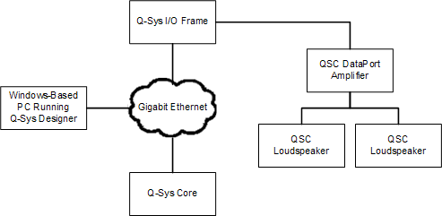
This topic is intended to give a high-level procedure for getting a simple Q-SYS system connected, running a Q-SYS design, and passing audio. The simple system consists of the following components:
- Ethernet Network
- Q-SYS Core
- Q-SYS I/O Frame
- QSC DataPort amplifier
- QSC Loudspeakers
- PC with Q-SYS Designer and other required software installed (The PC is not a required part of a Q-SYS system, but it is required for design and setup of the system)
Related Topics
Simple Q-SYS System Diagram
Procedure
NOTE: Anti-virus software, installed on the computer with Q-SYS Designer, may have an impact on some of the Q-SYS Designer operations.
The following procedure assumes that you have a Q-SYS Designer file containing these components properly connected, but not necessarily configured.
- Set up network.
- Q-LAN Networking
- Networked Audio Design
- Connect PC, Core and I/O Frame to the network.
- Q-SYS Core (hardware description)
- Q-SYS I/O Frame (hardware description)
- PC (requirements)
NOTE: When connecting a PC to the Q-SYS network it is usually necessary to purge information about a previous network connection to ensure successful connection to the new network. to do this, disconnect the PC from the original network, reboot the PC. Or, ensure you have administrator privileges on the PC, open a Command window, execute an ipconfig /release.
- Connect DataPort amplifiers and loudspeakers
- Amplifier & Loudspeaker Integration
- Power up the equipment:
IMPORTANT: Proper power turn on/turn off sequencing can help to prevent unexpected sounds from being produced by the system (pops, clicks, thumps). These unintended sounds can be unpleasant and take away from the overall professionalism of the presentation.
- Always follow the rule that speakers are “last on, first off”.
- Power On Sequence: Bring the output level controls of all audio source equipment to their minimum positions.
- Turn on all source devices (Core, I/O Frame, Page Stations, etc.). The Core and I/O Frames do not have power switches, simply plug them to the proper power source.
- Turn on all amplifiers. Refer to the individual user manuals for instructions on the other equipment.
- To turn off the equipment, repeat this procedure in reverse.
- On the PC:
- Start Q-SYS Designer
- From the main menu, select Tools > Show Configurator.
- In the Configurator list, click the Q-SYS Core. The Core's network settings display.
- Review/configure the Core's network settings
- A new Core is shipped with both LANs enabled, and the addressing Mode set to Automatic.
- DHCP Server - If there is a DHCP server on the network, the IP Address is automatically assigned.
- Link Local address - if there is not a DHCP server on the network, the address is automatically assigned, starting with 169.
- Static IP Address - Set the Mode for the LAN and assign a static IP Address, Mask and Default Gateway.
- Off - If you do not have a redundant network, set the Mode for LAN-B to Off.
- The Core is shipped with a default Name, rename the Core to match the name in your design.
- In the Configurator list, click the Q-SYS I/O Frame you wish to configure. The I/O Frame's network settings display.
- A new I/O Frame is shipped with both LANs enabled, and the addressing Mode set to Automatic.
- DHCP Server - If there is a DHCP server on the network, the IP Address is automatically assigned.
- Link Local address - if there is not a DHCP server on the network, the address is automatically assigned, starting with 169.
- Static IP Address - Set the Mode for the LAN and assign a static IP Address, Mask and Default Gateway.
- Off - If you do not have a redundant network, set the Mode for LAN-B to Off.
- The I/O Frame is shipped with a default Name, rename the I/O Frame to match the name in your design.
- In the same way, configure any other Q-SYS devices connected to your network.
- Start Q-SYS Designer
- Open your design file.
- Select the Core in the Inventory list, and verify the configuration. Refer to the Core topic.
- Ensure that the Core's Name in your design matches the Name in Q-SYS Configurator.
- Select the I/O Frame in the Inventory list, and verify the configuration. Refer to the I/O Frame topic.
- Ensure that the I/O Frame's Name in your design matches the Name in Q-SYS Configurator.
- Ensure that the amplifier is properly connected in the design and configured correctly. The connections and configuration should match the physical connections. Refer to the Amplifiers Overview and select the topic for your amplifier.
- Ensure that the loudspeakers are properly connected to the amplifier in the design, and configured correctly. The connections and configuration should match the physical connections. Refer to the Loudspeakers Overview and select the topic for your loudspeakers.
- There are many ways to pass audio through the Q-SYS system, your design should contain one or more ways to do this. If not, refer to the Online Help and add components that would allow you to pass audio.
- Save the design to the Core and connect (Press F5). Refer to the Main Menu topic and About Designs on the Core.
- If the Core's firmware does not match that of Q-SYS Designer on your PC, you are prompted to update the firmware. Refer to Updating Q-SYS Software and Firmware. Note: To download the latest Q-SYS Designer software and firmware, go to http://www.qsc.com.
- Test the system.
- Before trying to pass audio, place the System Mute component in your design, Emulate the design (F6), and click the Mute button. When you attempt to pass audio for the first time, you can un-mute the system and the output will ramp up to the level of the settings in your design. If they start to get to loud, you can press the mute button again and make necessary adjustments.
- Enjoy!
© 2009 - 2016 QSC, LLC. All rights reserved. QSC and the QSC logo are trademarks of QSC, LLC in the U.S. Patent and Trademark office and other countries. All other trademarks are the property of their respective owners.
http://patents.qsc.com.